A Swarm of Xbees! Arduino Xbee Wireless & More

Everyone hates long wires running from one end of the room to the other, and let’s face it, it's aesthetically unpleasant. So, why not make your next project a little bit more interesting and easy to use by adding wireless communication capabilities? In this post we will be using the the series 1 XBee modules to make this happen. This particular version of the XBee is perfect for applications where you need low-power consumption, easy integration, and great distance.
Series 1 vs Series 2/.25
A quick note here: This article does not cover the series 2 or series 2.5 XBee modules, and the series 1 and 2/2.5 are not compatible with each other. If you are looking to create mesh-networks, or multi-point to single-point networks, this is not for you, and you want the series 2/2.5. If you want ease-of-use, have low security requirements, and are basically looking to replace your wired serial connection with a wireless solution, the series 1 XBee is perfect.
Furthermore, the series 2/2.5 is not meant to replace the series 1... They are just different and live side by side, so don't feel like you are buying obsolete technology with the series 1.
As I alluded to above, these modules are basically a wireless UART serial connection, so you can communicate with anything that uses UART (has the RX/TX pins). And when series 1 XBees are properly configured, sending data through the RX pin on modules will cause that exact same data to just come pouring out the TX pin on all other XBees in range as if they were wired together. Simple as that.
Choosing the right one for you
XBees come with different antennas, and power ratings, so depending on what your requirements are, the modules will cost you anywhere from $20 to $70 and are available from your favorite vendor like Sparkfun. If you are not sure what you need, go with the 1mW chip antenna version, and you usually can't go wrong.
Each module has its own advantages and disadvantages, and you should choose them considering your individual requirements.
- Wire antennas offer omnidirectional (When the antenna is straight, the maximum transmission distance is equal in all directions.)
- The chip antenna is a flat ceramic chip. It takes up less space than the wire antenna, but the signal is not as omnidirectional as the wire antenna.
- The U.FL connector is the smallest of the external antenna connectors. You can use the XBee without attaching an antenna to this connector, but if your project is inside a metal case, you will need to attach an antenna and make sure it pops out. If you don’t, the signal will be attenuated by the metallic case.
getting started
At the very minimum, you are going to need at least 2 XBee modules... But we also reccomend using either an XBee shield, or XBee ready Arduino, as well as an XBee explorer if you want to change the XBee's default configuration. So, yes, it can get expensive, but you are opening a lot of new possibilities for your projects.
Hooking one up
The supply voltage for the XBees is 3.3 volts, and it is a strict 3.3v. Sending a 5v serial commend to them from your Arduino can flat out kill them, so pay close attention when connecting so you don’t fry your circuits.
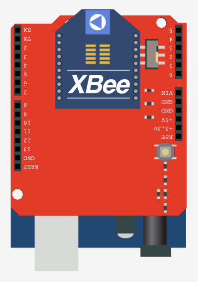
Arduino in its many forms has made this easy for you, you can purchase an XBee shield that will take care of all of this, or they even sell XBee ready Arduinos like the Arduino Fio (requires an external usb programmer). These guys are going to do everything for you as far as getting the XBee connected to your arduino goes.
If you are using an Arduino and have no XBee shield, or you want to go completely Arduino-less, you still have options. If your arduino is a lillypad or other 3.3v arduino this will be easier, and nothing else is really needed. If you are like 95% of us and all your arduino's are 5v arduinos, this is only slightly harder. The 5v arduinos like the duemilanove and the uno all communicate at 5v. That means that even if you power something up using the 3.3v pin, the serial, digital pins, everything, are all still operating at 5v. Sometimes this is not an issue, but with the XBee it is. But there is a way to convert the 5v to 3.3v using something called a logic level converter. The logic level converter steps the 5v down to 3.3v for safe communication. It also works the other way around, the 3.3v serial from the xBee will be converted to 5v serial for the Arduino.
If you decide to go this way, note, the XBee is not breadboard friendly, so you may want a breakout board unless you want to solder directly to the pins. Sparkfun does offer a board that acts as a brekout board and logic level converter in one, but, based on the comments, it sounds like a lot of people are having issues with it, so be forewarned.
The logic level converter needs to be powered by both 5v and 3.3v, and has several ins/outs. So look to the schematic on the right to get this all figured out.
The XBee itself really only needs 4 connections to operate. Power, ground, and RX/TX. If you have this hooked up to a sensor that is only transmitting data (Like the RFID reader), you could even get away with 3 connections. The XBee has many other pins on it like read/write LED pins so you can see when it is communicating, but these are't required.
Configuring the XBees
XBees are actually ready to use out of the box. They all come configured on channel 0X0C (12), operating on network 3332, and use a default baud rate of 9600bps. What this means is that without changing these settings, they will just talk to each other. But it also means that anyone else (in range) who also hasn't changed these setting can communicate with them as well. If this is not an issue for you, you can actually skip the rest, you are done. Just remember that someone's command to read a value, could be your command to self-destruct, so if you wonder why your robot just jumped off a cliff, it could be because someone with the same settings just came into range. So... if you would like to change these settings and make your wireless a bit more secure, keep reading.
To reconfigure your XBee, you are going to need a way to connect it with your computer. For this we use the XBee Explorer USB. This requires the FTDI drivers to work, but of your computer is already setup to wotk with a pre-UNO arduino, you actually already have this installed. To talk to the XBee you will need the XCTU software (windows), or a serial terminal like ZTERM. The arduino software does have a serial terminal, but it wont work for this. (it needs to be able to transmit without line end characters)
To reconfigure the XBee, first plug the XBee onto the explorer making sure it is facing the right direction (use the white outline as a reference) then plugin the explorer to your computer.
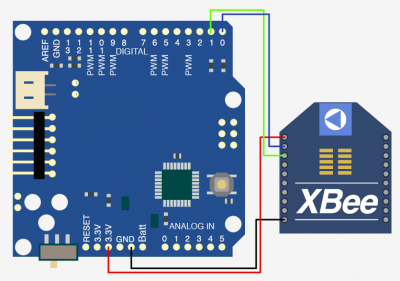
3.3v Arduino Pro connected directly to the XBee Module
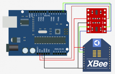
5V Arduino connected to XBee using a Logic Level Converter
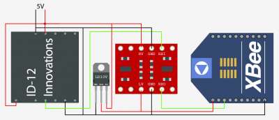
ID-20 RFID reader, sending data through XBee without a microcontroller
Windows Computer
First, download and open the XCTU application. Check the different tabs at the top. From PC Settings, you will have to choose the correct COM port. After selecting it, you should see basic information on your current configuration (baud rate, flow control, data bits, parity and stop bits). The Range Test tab allows you to check the communication range. This range depends on the materials interfering with the line of sight (walls, furniture, etc.) and other signals in the environment, portable phones, microwaves, other XBee networks... From the Terminal tab you will be able to send data and see any received information. The Modem Configuration tab will allow you to make changes to the current configuration.
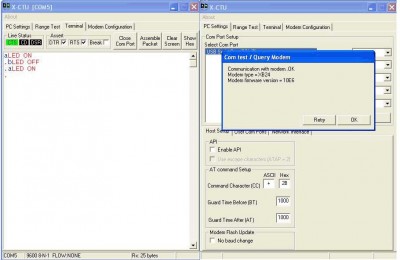
For this tutorial we will be focusing on the PC Settings, Terminal, and Modem Configuration tabs, but feel free to explore the Range Test tab. After selecting the correct COM port in PC Settings and checking out the basic information, click the Test/Query button. A window should (see picture blow) pop up indicating some information about your XBee. If nothing pops up, try again, and make sure the xbee and explorer are connected correctly. If it still does not work, your XBee could be malfunctioning and may need to contact the manufacturer for support.
Now open the Modem Configuration tab, and click on the Read button to check the current configuration.
At this point you may be required to download some updates. If this is the case, click on the "Download new versions" button. Use the web as the source, and wait for the download. After the updates are installed, press the Read button.
The white box should start populating with the actual configurations. In order to change them, double click on the value and entered in the desired value. If you want, you can up the baud rate in order to speed up transmission.
Make sure to note the channel your XBee is working on. Once finished with the first xbee, do the same to the second making sure the channel, network id, and baud rate are the same. All of your XBees will need to be have the same channel and the same settings under “Serial Interfacing” to be able to communicate with each other. Different channels are available in case there are other XBees projects nearby as even operating on different network IDs, nearby XBees on the same channel can cause interference and reduce the achievable distance.
You should now have both XBees with the same configuration. Leave one xbee on the explorer and mount the shield on top of the Arduino, but do not place the xbee on the shield (or connect it to your arduino) just yet.
Non-Windows computer
Unfortunately the XCTU application is windows only, but if you are on a mac, or linux, you are not at a complete loss. Using your favorite terminal application you can do most of the configuration via the command line. For this demo, I we will be using ZTerm for Mac OSX.
After you have the XBee connected to the explorer, and the explorer connected to to your computer, go ahead and open ZTerm. A window may pop up asking what you what serial port you would like to connect to, select the one with the funny name, it should start with "usbserial" - Mine was usbserial-A8007ZVm. If it does not come up, after zterm has finished launching, go to the settings menu and select "Modem Preferences". Under "Serial Port" select the one as described above (image below). Now go back to the settings menu and select "Connection..." Here we need to change a few things. Make sure to configure this just as I have mine in the image below, especially making sure that the baud rate is set 9600. The terminal should be all ready to communicate with the XBee.
Now that that is all done, we are going to send commands to the XBee to set configurations. This will feel a little weird at first, but you will be ok. When you type, you will not see it in the terminal window. This is normal! Some of the commands you do not press enter after, so remember that! Also, if you dont enter commands after a few seconds, you have to nudge it again by entering the attention command again.
You can change a lot of the setting from here, but im only going to cover changing the network ID. For more information on changing other settings through the terminal check out this page.
In the terminal window we are going to call the attention of the XBee by typing +++ DO NOT PRESS ENTER - but you should see "OK" appear once you do it. If you wait too long before you type another command, the XBee will stop responding to your requests. If this happens, just type +++ again.
First, just to make sure it is all working, type ATID and hit enter (Henceforth noted as
Now that the settings are saved, you need to apply these same settings all XBee modules you want on the same network, or they wont be able to communicate with each other.
Post Configuration
Now that all of your XBee modules are all set up and on the same network the way this will work is that any incoming data on that RX pin on any XBees on the network will cause that same data to come out of the TX pin of all the other modules on the network and vice versa. So... If you have 10 XBees on that network, they will all receive any data that any of them transmit. This is pretty cool I know! Just note that the serial buffer can get filled pretty quickly so if you are transmitting too much data constantly, you can get lost packets and some of the data may not transmit properly.
Also, if you have an XBee on an xbee explorer connected to your computer, and you have your arduino serial monitor open (you will need to select the explorer just as you would an arduino to be able to read from it), you can send and receive commands to the xbees on that network using this. This also means that the wireless RFID diagram above could send that RFID tag to an XBee connected to an Arduino, or a computer.
So we have a few code examples that show both of these happening.
Code
Because the Arduino is actually programmed through the same RX/TX pins the xbee will be using, it is not possible to program your Arduino while the XBee is connected to it. So you need to make sure to remove the XBee from the Arduino when you go to upload a new sketch.
For our first code example, we have put together an extremely simple computer to Arduino sketch where we are going to send data from the computer to the Arduino and vice versa. Sending "a" from the computer terminal window will turn on the LED on pin 13 of the Arduino, and sending "b" will turn it off.
You can also send this data from XCTU as well in the Terminal tab. Type an ‘a’. Check your Arduino's LED under the shield. It should be on. Type ‘b’ to turn it off. You can also send data from the Arduino to the computer just as you normally would using Serial.print(). This can be really helpful in getting a response back after you send a command.
//////////////////////////////////////////////////////////////////
//©2011 bildr
//Released under the MIT License - Please reuse change and share
//Monitors the serial port to see if there is data available.
//'a' turns on the LED on pin 13. 'b' turns it off.
//////////////////////////////////////////////////////////////////

void setup() {
  Serial.begin(9600);    	//initialize serial
  pinMode(13, OUTPUT);   	//set pin 13 as output
}

void loop() {
  while(Serial.available()){  //is there anything to read?
	char getData = Serial.read();  //if yes, read it

	if(getData == 'a'){
  	  digitalWrite(13, HIGH);
	}else if(getData == 'b'){
  	  digitalWrite(13, LOW);
	}
  }
}
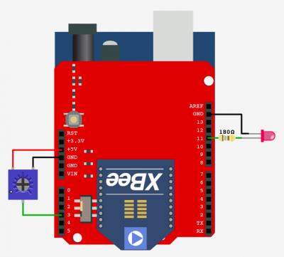
The second example requires 2 or more Arduino/XBee combos that are exactly the same. See the diagram above with the potentiometer and LED connected to it.
What this does: Turning the potentiometer on one Arduino, will change the brightness of all the others on the network.
//////////////////////////////////////////////////////////////////
//©2011 bildr
//Released under the MIT License - Please reuse change and share
//Turning the pot on one Arduino, dims the LED on all the others on the network
//////////////////////////////////////////////////////////////////

#define potPin 3
#define ledPin 11


int inByte = -1;
char inString[6];
int stringPos = 0;
int lastValue = 0;


void setup()  {
  pinMode(ledPin, OUTPUT);
  Serial.begin(9600);
}

void loop() {
   inByte = Serial.read();

   //only send new value if it is different than last sent value.
   //Min value change of 5 neded. Just so we dont flood the network
   int potVal = analogRead(potPin);
   if( abs(potVal - lastValue) > 5){
     Serial.println(potVal);
     lastValue = potVal;
   }

  //if there is any numerical serial available, store that
  if((inByte >= '0') && (inByte <= '9')){
    inString[stringPos] = inByte;
    stringPos ++;
  }

  //if there is a line end character, this string is done, take value and write to LED pin
  //clear the string when done
  if(inByte == '\r'){
    int brightness = atoi(inString); //convert string to int

    //incoming will be a range of 0-1023, we need 0-255
    brightness = map(brightness, 0, 1023, 0, 255);
    analogWrite(ledPin, brightness);


    //clear the values from inString
    for (int c = 0; c < stringPos; c++){
      inString[c] = 0;
    }
    stringPos = 0;
  }

}
Extending This
Now that you have the basis on XBees, try working with more than two XBees. Create different network topologies and try different configurations. Explore how walls and other objects affect the range of the signal transmission. If you really cant think of something right away, use two arduinos to make a wireless RFID door lock converting this tutorial. Or take control of your Arduino's pins wirelessly converting this tutorial. But really, who cant think of something that could be made cooler using wireless?
Article taken from bildr.org with minor changes - I am the original author of this content
