Getting started with your SparkFun EL Sequencer

So you bought your self a fancy new EL Sequencer from SparkFun and your wondering how to use it... Aside from the product page being totally ambiguous, there doesn't seem to be much help out there on how to get started with this - So I thought I would put an end to that.
About The Board
You may not know it, but you actually bought yourself a full-blown arduino that can be used to switch EL Strands on and off. Yes, you read that right... The EL Sequencer is an Arduino, and it just has the digital pins connected to TRIACs so you can switch the high-voltage, high-frequency signal that is needed to power the EL Wire. The reason for the embedded microcontroller is so it can be a standalone part and not require anything else to control it. If you are more of a pure AVR/C person, the sequencer can be programmed with your favorite IDE as well, but this article will cover programming it as an arduino.
Hooking It Up
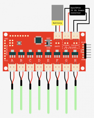
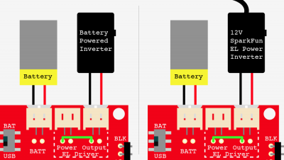
Of all things that complicated the setup for me, this was it. The text on the sequencer is a little ambiguous, but I did some searching, and checked with SparkFun, and this is how it goes. The image on the right assumes you have the 3v SparkFun El Inverter - The weirdest part for me was that both sides of the inverter are plugged into the sequencer, but this allows a single battery to power the sequencer and the inverter. And, if you do it like this, the USB/Batt switch can be used as a power switch. Lastly you need a power source. The battery plug can be powered with anyting 3 - 4.2v but works particularly well with the 3.7V liPoly batteries.
But I have a different inverter!
Yeah, there are a lot of inverters out there, and most are not double ended like the 3V inverter is. If that is the case with the one you own, have no fear, we just need to do things a little differently. Sadly, this will require 2 power sources, and you will need to switch off the inverter and the sequencer separately, but this will work. To make this work, a wire needs to be soldered between the "power" and the "output" of the EL Driver section as shown on the right (look for the green line).
Even though your inverter is powered and connected to the sequencer, the sequencer still needs power for the arduino part. If you are not using the 3v inverter loop, the battery input on the sequencer can range anywhere from 3-12V.
Programming The Sequencer
To program your EL sequencer you need some way to get the code on there. I am using the FTDI basic from SparkFun as shown in this illustration, but you can use an FTDI cable as well. You just need some way to get a USB connection to the board. You will also need to solder some pins onto the right of EL Sequencer where it says USB so you can plug the programmer into it.
Once you have the sequencer connected to your computer via the FTDI basic you are good to go. If you switch the switch on the sequencer to usb, you will see the board power up. In the Arduino IDE you need to select the proper serial port, and under "board" you are going to select "LilyPad Arduino w/ ATmega 328". If you have an older version of the EL sequencer, you will want to select "LilyPad Arduino w/ ATmega 168".
Code
The example he have is dead simple. But I wanted to show you how it was basically just a regular arduino. All it does is blink all the channels. If you want to fade the EL wire you can not simple use analogWrite or PWM - The EL wire acts as a capacitor and prevents it from working well regular PWM.
If you want better contol, and fading, I reccomend using SparkFun's EL_Escudo library, (they figured out the fade). It has blink commands, all_off commands, fading, you name it. You can get that here - Just make sure to place it in your arduino's library folder, and you need to restart the arduino software before you can use it.
#define A  2
#define B  3
#define C  4
#define D  5
#define E  6
#define F  7
#define G  8
#define H  9

void setup(){
  pinMode(A, OUTPUT);
  pinMode(B, OUTPUT);
  pinMode(C, OUTPUT);
  pinMode(D, OUTPUT);
  pinMode(E, OUTPUT);
  pinMode(F, OUTPUT);
  pinMode(G, OUTPUT);
  pinMode(H, OUTPUT);
  }


void loop(){
     digitalWrite(A, HIGH);
     digitalWrite(B, HIGH);
     digitalWrite(C, HIGH);
     digitalWrite(D, HIGH);
     digitalWrite(E, HIGH);
     digitalWrite(F, HIGH);
     digitalWrite(G, HIGH);
     digitalWrite(H, HIGH);

    delay(2000);

    digitalWrite(A, LOW);
     digitalWrite(B, LOW);
     digitalWrite(C, LOW);
     digitalWrite(D, LOW);
     digitalWrite(E, LOW);
     digitalWrite(F, LOW);
     digitalWrite(G, LOW);
     digitalWrite(H, LOW);

     delay(500);


}
Other
Just note that the EL wire is 100+V at 4000hz, but very low power. And while you wont feel a shock, if you touch the sequencer in the wrong places, you will tingle. So if you have this in a costume or something, make sure it is properly covered.
Also, if you are looking for a great tutorial on cutting and splicing EL Wire, Lady Ada has you covered in this great article.
Thanks to apothus for this additional info.
Article taken from bildr.org with minor changes - I am the original author of this content


