L3G4200D Tripple Axis Gyroscope + Arduino

The L3G4200D is a 3-axis angular rate sensor, aka gyro/gyroscope with a user selectable 250, 500 or 2000º/Sec scale. I was about to write about what a gyro is, but Sparkfun has done a really great job of that, so to quote them:
Gyroscopes measure angular velocity, how fast something is spinning about an axis. If you're trying to monitor the orientation of an object in motion, an accelerometer may not give you enough information to know exactly how it's oriented. Unlike accelerometers gyros are not affected by gravity, so they make a great complement to each other. You'll usually see angular velocity represented in units of rotations per minute (RPM), or degrees per second (°/s). The three axes of rotation are either referenced as x, y, and z, or roll, pitch, and yaw.
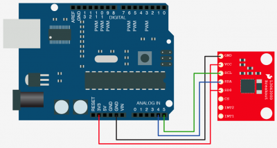
Hooking It Up
The L3G4200D has a lot of pins on it because it supports both SPI and I2C but also has some other features as well such as programmable interrupts. We are going to go as simple with this as possible.
The L3G4200D supports both SPI and I2C, but we are just going to talk I2C here. I2C is a 2-wire serial connection, so you just need to connect the SDA (Data) and SCL (Clock) lines to your Arduino for communication. On your Arduino (everything but the mega) SDA is on analog pin 4, and SCL is on analog pin 5. On an arduino mega, SDA is digital 20, and SCL is digital 21.
But other than Power, Ground, and the I2C pins, we just need to connect SD0 to 3.3v (to set the I2c Address).
Code
The code for this is a little complex mainly because it is a digital device. But I tried to simplify it as much as possible for you. You may have noticed that Sparkfun already had a code example written. Yep... And part of this code is based on that. I actually decided to write new code for 2 reasons. 1: Their code is CreativeCommons licensed. I like MIT better because you are more free to do what you need with it. 2: I like I2C better than SPI - Why? 2 less wires!
This code just outputs the x,y,z axis angular rate (in deg/sec) in the serial terminal. Simple as that.
According to the data sheet, this is all correct. But when the sensor is sitting still and is set to 2000º/sec, I am seeing readings of 0-70 on all 3 axises. I know gyros drift, but this seems weird. If someone knows what is going wrong here please let me know.
#include <Wire.h>

#define CTRL_REG1 0x20
#define CTRL_REG2 0x21
#define CTRL_REG3 0x22
#define CTRL_REG4 0x23
#define CTRL_REG5 0x24

int L3G4200D_Address = 105; //I2C address of the L3G4200D

int x;
int y;
int z;

void setup(){

  Wire.begin();
  Serial.begin(9600);

  Serial.println("starting up L3G4200D");
  setupL3G4200D(2000); // Configure L3G4200  - 250, 500 or 2000 deg/sec

  delay(1500); //wait for the sensor to be ready
}

void loop(){
   getGyroValues();  // This will update x, y, and z with new values

  Serial.print("X:");
  Serial.print(x);

  Serial.print(" Y:");
  Serial.print(y);

  Serial.print(" Z:");
  Serial.println(z);

  delay(100); //Just here to slow down the serial to make it more readable
}

void getGyroValues(){

  byte xMSB = readRegister(L3G4200D_Address, 0x29);
  byte xLSB = readRegister(L3G4200D_Address, 0x28);
  x = ((xMSB << 8) | xLSB);

  byte yMSB = readRegister(L3G4200D_Address, 0x2B);
  byte yLSB = readRegister(L3G4200D_Address, 0x2A);
  y = ((yMSB << 8) | yLSB);

  byte zMSB = readRegister(L3G4200D_Address, 0x2D);
  byte zLSB = readRegister(L3G4200D_Address, 0x2C);
  z = ((zMSB << 8) | zLSB);
}

int setupL3G4200D(int scale){
  //From  Jim Lindblom of Sparkfun's code

  // Enable x, y, z and turn off power down:
  writeRegister(L3G4200D_Address, CTRL_REG1, 0b00001111);

  // If you'd like to adjust/use the HPF, you can edit the line below to configure CTRL_REG2:
  writeRegister(L3G4200D_Address, CTRL_REG2, 0b00000000);

  // Configure CTRL_REG3 to generate data ready interrupt on INT2
  // No interrupts used on INT1, if you'd like to configure INT1
  // or INT2 otherwise, consult the datasheet:
  writeRegister(L3G4200D_Address, CTRL_REG3, 0b00001000);

  // CTRL_REG4 controls the full-scale range, among other things:

  if(scale == 250){
    writeRegister(L3G4200D_Address, CTRL_REG4, 0b00000000);
  }else if(scale == 500){
    writeRegister(L3G4200D_Address, CTRL_REG4, 0b00010000);
  }else{
    writeRegister(L3G4200D_Address, CTRL_REG4, 0b00110000);
  }

  // CTRL_REG5 controls high-pass filtering of outputs, use it
  // if you'd like:
  writeRegister(L3G4200D_Address, CTRL_REG5, 0b00000000);
}

void writeRegister(int deviceAddress, byte address, byte val) {
    Wire.beginTransmission(deviceAddress); // start transmission to device
    Wire.write(address);       // send register address
    Wire.write(val);         // send value to write
    Wire.endTransmission();     // end transmission
}

int readRegister(int deviceAddress, byte address){

    int v;
    Wire.beginTransmission(deviceAddress);
    Wire.write(address); // register to read
    Wire.endTransmission();

    Wire.requestFrom(deviceAddress, 1); // read a byte

    while(!Wire.available()) {
        // waiting
    }

    v = Wire.read();
    return v;
}
Article taken from bildr.org with minor changes - I am the original author of this content
